
 | marketing@wsdks.com |  | +8617712621386 |  | No. 8 Jinwei Road, Changshu City, Jiangsu Province, P.R.China |


How to Achieve Zero Liquid Discharge in a Fab
A fab ZLD program starts with stream mapping. How to achieve zero liquid discharge in a fab depends on where water is used, which process creates each wastewater stream, what can be reduced or reused, and how remaining constituents and solids will leave the defined boundary. One end of pipe unit cannot replace this site wide material balance.
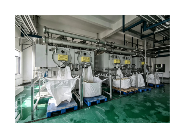
The zero liquid discharge solution categories provide a starting point for commercial discussion. This guide remains industry general and does not claim VIFLUTER semiconductor project experience, a fixed recovery, or a universal fab design.
How to Achieve Zero Liquid Discharge in a Fab
First define the boundary. It may cover one process area, a difficult segregated stream, a building, or the full facility. List every water input, process use, reuse loop, wastewater source, storage tank, treatment stage, liquid outlet, cleaning waste, concentrate, sludge, and solid route. A ZLD claim is incomplete when an intermittent or emergency liquid outlet remains outside the accounting method.
The objectives should state required production reliability, water supply reduction, recovered water uses, treatment handoffs, and residual endpoints. They should also identify the operating conditions that the system must manage, including startup, product change, maintenance, upset, and expansion. No single recovery target should be applied before this basis is agreed.
Map and Segregate Fab Wastewater Streams
Semiconductor and electronic component manufacturing can generate wastewater from etching, cleaning, degreasing, cutting, grinding, and related operations. The EPA Electrical and Electronic Components page identifies fluoride, arsenic, and organic compounds among possible wastewater pollutants in its sector description. These are examples from the official category and should not be assumed in every fab or every process area.
Build the stream map at the tool or process group level where practical. Record flow, timing, temperature, pH, conductivity, acids or alkalis, fluoride, metals, oxidants, reducing agents, organics, particles, and other process chemicals as applicable. Keep lower load or compatible streams separate from concentrated or reactive streams when the piping, controls, and production risk support that choice.
Build the Water and Constituent Balance
A water balance should connect incoming water, ultrapure water production where relevant, point of use demand, rinse flows, cooling or utility uses, reclaim, treatment losses, storage changes, and residual outlets. Use normal, peak, batch, maintenance, and upset conditions. Mark measured values separately from estimates and identify the sampling period.
Water volume alone is not enough. Track the mass or load of the constituents that control pretreatment, membrane concentration, evaporation, crystallization, and residual handling. A source reduction step may lower water use while increasing concentration. The downstream process must be evaluated against both changes.
Reduce Demand and Design Reuse Cascades
Potential source reduction actions may include repairing uncontrolled flows, optimizing rinse sequences, separating first rinses, improving tool shutoff, or reusing a suitable stream in a less demanding application. Each change requires confirmation that product quality, equipment protection, worker safety, and process control are maintained.
Fit for purpose reuse matches a recovered stream with a sink that can accept its quality and timing. The U.S. EPA notes that different recycled water sources and end uses may require different treatment and monitoring. Define the receiving use, quality parameters, storage, backup supply, off specification route, and owner before relying on the reuse in the facility balance.
Define Pretreatment by Stream
Feed issue | Possible treatment duty | Questions before selection |
Particles or precipitated solids | Equalization, clarification, filtration, or another suitable solid liquid separation | What particle size, variability, chemical addition, backwash, and sludge route apply |
Fluoride or metals where present | Speciation based precipitation, adsorption, ion exchange, membranes, or another validated sequence | What species, complexants, pH, competing ions, endpoint, and residuals control the choice |
Acidic or alkaline streams | Segregation, controlled neutralization, recovery, or compatible blending after review | What heat, gas, precipitation, corrosion, and reaction risks exist |
Organic or solvent related load where present | Source isolation and a treatment method selected for the identified compounds | Which compounds are present, are they volatile, and how could they affect condensate or residual classification |
The table lists functions rather than a fixed sequence. Treatability tests should use representative process water and answer a defined handoff question. Pretreatment additives can affect membranes, evaporation, crystallization, and residuals, so the full train needs a chemical and mass balance.
Use Membrane Concentration Where the Feed Permits
Membranes may recover water and reduce the flow sent to thermal treatment. Their useful operating range depends on osmotic pressure, scaling, organic fouling, particles, oxidants, temperature, pH, membrane selectivity, and the required permeate quality. Different membrane processes perform different separations and should not be grouped as interchangeable.
Define pretreatment, recovery envelope, permeate destination, reject composition, cleaning waste, monitoring, and off specification routing. A short clean water test does not establish long term behavior on mixed fab wastewater. Pilot work may be needed when chemistry or variability creates material uncertainty.
Finish the Concentration and Solids Route
Evaporation can remove additional water from a concentrated stream, and crystallization or dewatering may support a nonliquid residual route. VIFLUTER's industrial wastewater ZLD process illustrates one possible staged arrangement. It should not be treated as the only valid fab flow sheet.
Thermal design should address boiling point elevation, scale, corrosion, foam, suspended solids, volatile compounds, heat transfer, condenser duty, cleaning, and materials. Condensate needs a quality objective and monitoring before a defined reuse. The remaining concentrate or slurry needs a stable transfer, storage, dewatering, and final destination.
Design Reliability and Change Control
Fab utilities support production schedules that may place a high value on availability. Define storage, parallel capacity, standby equipment, bypass policy, alarm response, spare parts, maintenance access, and the route for off specification water. The required redundancy depends on the production consequence, feed variability, maintenance plan, and available buffer capacity.
Change control should connect process chemistry and production changes to the wastewater design basis. A new chemical, tool, product, cleaning sequence, or reclaim sink can change flow, speciation, fouling, volatility, or residuals. The water team should review those changes before the operating envelope or reuse claim is extended.
Plan Residual Characterization and Responsibility
The residual inventory can include pretreatment sludge, membrane concentrate, regenerant, spent media, filter backwash, evaporator concentrate, crystal slurry, dewatered solids, and cleaning waste. Record composition, moisture, storage, transfer, and destination. Potential hazardous characteristics and regulatory requirements require facility and jurisdiction specific determination.
Assign ownership for sampling, records, off specification routing, residual decisions, and periodic review. ZLD moves constituent mass into smaller liquid or nonliquid outlets. It does not remove the need to manage that mass or verify every water reuse endpoint.
Implement the Fab ZLD Roadmap in Phases
·Establish the source and sink map with measured normal and peak conditions.
·Separate avoidable water use from necessary process demand and test safe reduction actions.
·Validate reuse matches with end use quality, storage, monitoring, and off specification routes.
·Pilot uncertain pretreatment, membrane, evaporation, or solids handoffs with representative feeds.
·Commission the full water and constituent balance across production and maintenance modes.
·Reopen the design basis when tools, chemicals, products, reuse sinks, or facility capacity change.
Use the Fab Stream Map as the Design Basis
How to achieve zero liquid discharge in a fab can be answered only after each stream, reuse sink, treatment handoff, and residual route is defined. To discuss an industry general roadmap, share the fab stream map and water balance with VIFLUTER together with chemistry, operating modes, reuse quality, reliability needs, utilities, and planned expansion.
Sources and Further Reading
·U.S. Environmental Protection Agency, Electrical and Electronic Components Effluent Guidelines, updated March 17, 2026.
·U.S. Environmental Protection Agency, Basic Information about Water Reuse, updated June 5, 2026.
·Tong and Elimelech, The Global Rise of Zero Liquid Discharge for Wastewater Management, Environmental Science and Technology, 2016.